Technical pages
RS232 to ICSP interface
Schematics
Operation
Boards
Principle
This technical page describes a programming interface for the 16 bits PIC and dsPIC processors of MICROCHIP using a RS232 link.
This interface, reserved to the most informed electronics specialists and controlled by the FORTH micro system emulator, makes it possible to be freed from the purchase of a commercial programming kit.

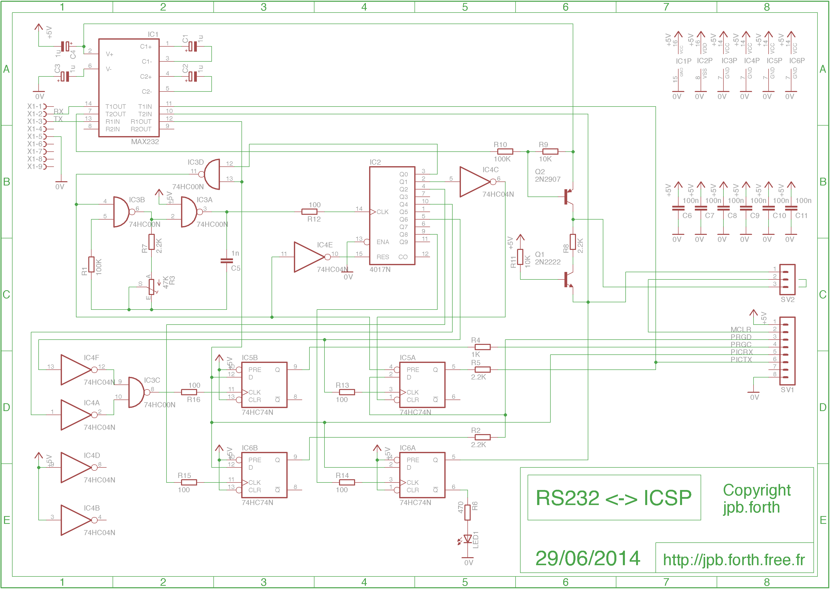
Schematics
Here is the interface schematic (
zoom):

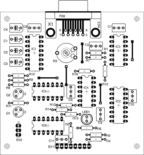
The components placement:
Operation
The interface manages only one bit by transmitted byte. This byte is compsed of 4 parts:
- the bits 0 and 1, which the value is 00b or 11b, drive the value of PRGD signal,
- the bits 2 to 5, which the value is 0000b,
0011b, 1100b or 1111b, sirve the value of PRGC signal with the ability of a positive or negative pulse,
- the bits 6 and 7, which the value is 00b ou 11b, drive the value of MCLR signal.
The various combinations make it possible to generate the sequences necessary to the use of ICSP programming.
Each transmitted byte causes the emission of a byte in return giving the value of PRGD (0xE0 for 1 or 0x00 for 0).
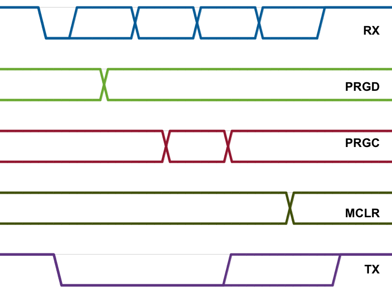
Here timing of the operation of this interface:
An indicator gives the state of MCLR signal
(lit if 0 or extinguished if 1). This indicator allows the adjustment
of the potentiometer R3 (frequency of reception the clock) by using
the adjustment procedure of the FORTH micro system emulator.
A strap makes it possible to choose the voltage applied to MCLR according to the used microcontroler during programmation (between pins 2 and 3 of SV2 for dsPIC24F and dsPIC30F, between pins 1 and 2 for the other one):
Terminal using (RS232)
|

|
| dsPIC24F and dsPIC30F programming |

|
| dsPIC24FJ/HJ/EP and dsPIC33FJ/EP programming |

|
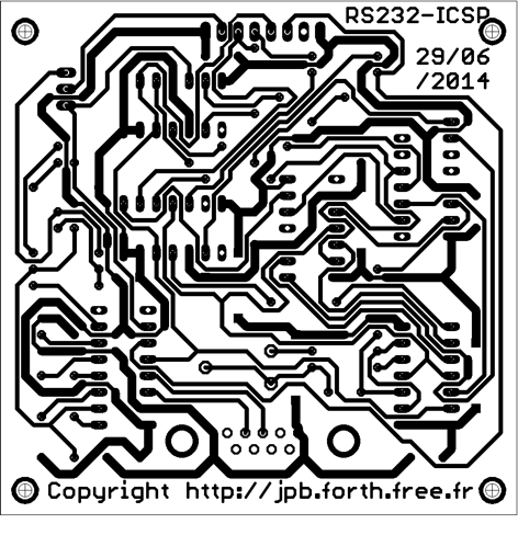
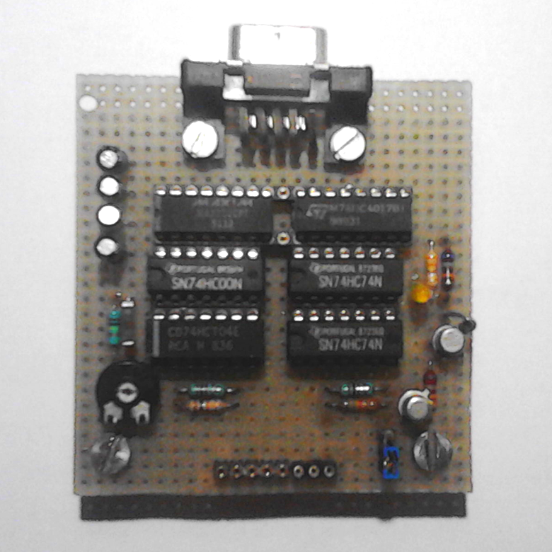
Boards
Here is the RS232 to ICSP interface prototype wired in wrapping:
Here is the final board: