Emulator analogical input output driver
Instructions
Use
Example
Principle
If the analogical input output of the emulator are addressable registers in
the extension registers area of the FORTH core described as follows:
274 (0x112) sampling
275 (0x113) analogical input output
if writing sampling = 0
-direct analogical input output
- reading sampling = 1
else
-2048 samples 10 us (1) to 8 samples 2,55 ms (255) FIFO
- reading sampling = available samples number
Analog range value must be -128 to +127
The driver will allow to facilitate the use of these registers while making
use of the real-time kernel. The principle consists in making i
possible the developer to conceive a program which is automatically
called during the samples flow.

Instructions
- CW_ECHANTILLONNAGE 274
Numero of the sample control extension register.
- CW_ANALOGIQUE
275
Numero of the analogical input output extension register.
adr_prg,periode SYNC_ANALOGIQUE -
Installation of the analogical input output driver.
adr_prg is the address of the program called with the input sample
and must give the corresponding output sample.
periode is the sample temporal value in us (10 minimum to 2550 maximum).
If adr_prg or periode is null, the driver is removed.
Use
The
driver not being integrated into the kernel, it is initially necessary
to compile the source file analogique.txt before being able to use it.
It is necessary to create the program called automatically by the driver by using following syntax:
: PROGRAMME
INSTRUCTION1
INSTRUCTION2 ... INSTRUCTIONn
;
WARNING: the program will have the value of the input sample on the data stack, it will must give an output sample.
It is then necessary to install the driver with the value of the desired periode:
FIND PROGRAMME PERIODE SYNC_ANALOGIQUE
The received sample FIFO is
read everys 20 ms and the program is called as many as there is
samples. With a 100 us periode for example, up to 200 samples will be
managed every 20 ms. Each sample from the program is send to the outpu
FIFO. This is
realized with priority 49152.
Example
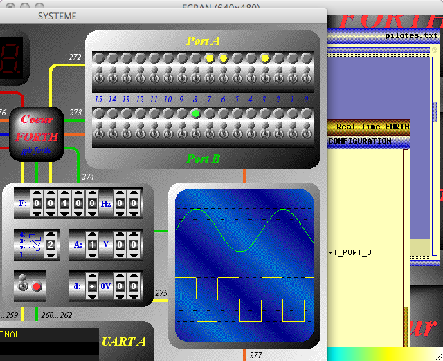
The following program is a software PLL multiplying by 2 the input frequency. The source file ports_A_B.txt mus
be also complide in order to the port A displays the output frequency
in binary mode and the port B displays the locking progression as a dot shifter:
DECIMAL
0 VARIABLE PERIODE
0 VARIABLE DIV
0 VARIABLE REF
0 VARIABLE FOSC
: PROG_ANALOGIQUE
( Input rising edge detection )
0< REF DUP >R @ OVER R> ! >R NOT R> AND NEGATE
( 1 Hz to 5 KHz oscillator )
PERIODE DUP >R @ FOSC @ - DUP 0<
IF
( Divided by 2 oscillator rising edge detection )
5000+ >R DIV DUP >R @ 1+ DUP R> ! 3 AND 2 = + R>
THEN
R> ! ?DUP
IF
( Frequency adjustment for locking )
FOSC DUP >R @ + DUP R> ! DUP >R SORT_PORT_A 1 R> 15 AND LSH SORT_PORT_B
THEN
( Oscillator output )
DIV @ 1 AND -200 * 100+
;
0 DUP SYNC_PORT_A 0 DUP SYNC_PORT_B FIND PROG_ANALOGIQUE 100 SYNC_ANALOGIQUE
To remove this program, it is enough to make:
65535 DUP SORT_PORT_A SORT_PORT_B 0 DUP SYNC_ANALOGIQUE
Here is a video: